With tooling having so many influential aspects that change the quality and cycle time of your part, it’s understandable to feel overwhelmed and want to learn more. One of these influential aspects is the runner system. The runner system controls the distribution of the plastic through the nozzle to the cavities. There are two main options when choosing your runner system, being a cold runner system or a hot manifold system. In this week’s blog, we will cover the cold runner systems, and in next week’s blog, we will cover hot manifold systems. To learn more about the other aspects of your tooling and how they can affect your part make sure to read 3 factors of the cosmetic appearance of your moulded part.
Cold Runner Systems
Cold runner systems are unheated moulds and channels used to inject molten plastic into a mould tool cavity. A cold runner injection moulding system consists of 2-3 plates for the mould. These two or three plates are used to inject plastic through the sprue and feed the runners that lead to parts in the mould cavity. This system utilizes a part called a sprue, that when designed correctly, will:
- Deliver melt to the cavities
- Balance filling of multi-gate cavities
- Minimise scrap
- Eject easily
- Maximise efficiency in energy consumption
- Control the filling/packing/cycle time.
These sprues are plastic components that will need to be ejected along with the part itself. Because of this, it is important that the sprue is designed without undercuts.
Sprue Bushing
The metal component that creates the sprue is called the sprue bushing. This sprue bushing connects the machine nozzle to the runner system and has a smooth, tapered internal finish to ensure clean ejection from the sprue. Normally it’s important that the sprue does not freeze before any other cross section in order to permit sufficient transmission of holding pressure.
Sprue Characteristics
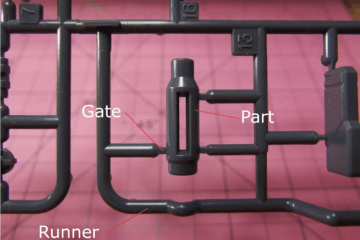
The sprue itself normally has a main runner, a branch runner (if it’s a multicavity tool), a cold slug well and gates. The main runner is the main entrance for the plastic to flow. If the tool is a multi cavity tool there will be branch runners coming off the main runner that send the plastic to each individual part. At the end of each branch runner, before the plastic can enter the part, the size of the gap becomes thinner creating a gate. This gate is designed to snap easily and helps when detaching the sprue from the parts. At the bottom of the sprue is a cold slug well. This is a small hole designed to trap any heavier bits of plastic to ensure there is no clogging in the tool.
Runner Layouts
The runner is important in ensuring that each part is filled equally and in a similar manner. The runner layout is particularly important when designing for this.
Unbalanced runner systems lead to unequal filling, post-filling and cooling of cavity features, which can cause problems like:
- Incomplete filling
- Shrinkage
- Warping
- Sink marks
- Flash
- Poor mould release
- Inconsistency
Another way to help perfect your runner system is to ensure that the diameter of your runner is smaller than the largest wall thickness of the product.
With a better understanding of the cold runner system, and the many aspects that it influences, you can design your product to be moulded more effectively, saving you both time and money.
Make sure to keep an eye out for next week’s blog, all about hot runner systems, for a full understanding of the runner systems available in your tooling. For more tips on creating the best possible tool, make sure to check out 3 tooling tips for creating the perfect part mould.
At Dienamics, we offer a range of comprehensive services in every step of the product manufacturing process. These include:
- Product design, including concept assessment and project scoping
- Prototyping and process and materials testing
- Manufacturing, injection moulding, production, assembly, and packaging
Contact us today if you have a product you’re looking to get designed & manufactured!
Subscribe to Our Newsletter
Get the latest news from Dienamics into your inbox